During design of pressure vessel, I came across this issue number of time.
Unfortunately, ASME VIII Div.1 doesn’t give a clear picture, whether to add the undertollerance in the min. required thickness as calculated by ASME VIII Div.1
ASME VIII Div. 2, give a clear cut understanding on this issue, can clears all ambiguity. (Clause 4.1.3)
The explanation goes as under
Mill Under tolerance. Plate material shall be ordered not thinner than the minimum required thickness.Vessels made of plate furnished with an under tolerance of not more than the smaller value of 0.3 mm (0.01 in.) or 6% of
the ordered thickness may be used at the full maximum allowable working pressure for the thickness ordered. If the specification to which the plate is ordered allows a greater under tolerance, the ordered thickness of the materials shall be sufficiently greater than the design thickness so that the thickness of the material furnished is not more than the smaller of 0.3 mm (0.01 in.) or 6% under the design thickness.
{The underline sentence is very clear, if they are in this limit, no need to add the allowance in calculation, which as per II-A, need to be part of purchase specification, and purchaser has to bid by it}
Pipe Under tolerance. If pipe or tube is ordered by its nominal wall thickness, the manufacturing under tolerance on wall thickness shall be taken into account. After the minimum wall thickness is determined, it shall be iincreased by an amount sufficient to provide the manufacturing under tolerance allowed in the pipe or tube specification.
{Again, this is very clear, we need to take this in account in our calculation}
So, Bottom line
If the shell is made from Plate (Rolled) and if purchase specs for Plate as per ASME II-A, then the vendor is binded to supply material within these limits, and we need not to consider additional allowance. But if your shell is made from Pipe, then you need to consider the 12.5% tolerance during calculation of thickness!
Hope this will help.
Like this:
Like Loading...
Whats is Earth quake factor? and how they affect the calculation?
Their are numerous papers on this, and they are equally qualified to tell you what is earthquake factor all about… but what mater to me is.. how do they do it!
As far as India is concern..The earthquake of 26 January 2001 in Gujarat was unprecedented not only for the state of Gujarat but for the entire country in terms of the damages and the casualties. As the state came out of the shock, literally and otherwise, the public learnt for the first time that the scale of disaster could have been far lower had the constructions in the region complied with the codes of practice for earthquake prone regions. Naturally, as Gujarat began to rebuild the houses, infrastructure and the lives of the affected people, it gave due priority to the issues of code compliance for new constructions.
Seismic activity prone countries across the world rely on “codes of practice” to mandate that all constructions fulfill at least a minimum level of safety requirements against future earthquakes. As the subject of earthquake engineering has evolved over the years, the codes have continued to grow more sophisticated.
Liquid storage tanks are commonly used in industries for storing chemicals, petroleum products, etc. and for storing water in public water distribution systems. Importance of ensuring safety of such tanks against seismic loads cannot be overemphasized.
Like this:
Like Loading...
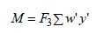
All designers are accustomed to evaluating moments due to eccentric and wind loads, but there are a few who may not be familiar with the method used for estimating moments due to earthquake. Therefore, the following brief outline is presented because this method is recommended as a design procedure for vessels where dynamic considerations are required. The weight of each vessel element (shell, head, tray, or internal part) is calculated. and then multiplied by the vertical distance from the circumferential seam (or horizontal plane) under
consideration to the center of gravity of the element. The summation of the moments so found ismultiplied by the seismic factor for the area where the vessel is to operate, thereby yielding a moment due to earthquake or seismic disturbance. For vessels, the seismic factor will usually have a value of 0.03 to 0.12, depending upon the geographical location. Expressed mathematically,
Like this:
Like Loading...
It is customary for most vessel designers to establish the minimum vessel shell and trend thickness according to the pressure temperature conditions and then calculate the thickness required at the bottom head seam due to bending moments imposed by wind or earthquake forces. Stresses in the longitudinal direction are involved nod the following notation may
be used to summarize the thickness required :
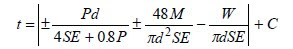
Here, The terms within the absolute value signs are positive for tensile stresses and negative for compressive stresses. The first term gives the thickness required for the longitudinal stress resulting from internal pressure and is positive for pressures above atmospheric and negative for pressures below atmospheric. The second term is the thickness required to resist the longitudinal bending stress and both positive and negative values exist at the same time. The third term is the thickness required for the weight of the vessel above the seam being investigated and, since this is a compressive stress, it has a negative value. The combination giving the highest value establishes the thickness required to resist the longitudinal stresses.
This formula hold good when the units are in Psi, ft & lb, if the units are in MPA, mm, N then remove the ’48’ from the formula.
Like this:
Like Loading...

